34
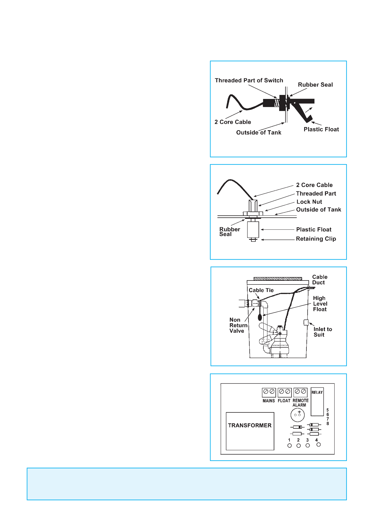
PTL1A (SIDE MOUNTED FLOAT)
1. Drill a hole in the side of the tank at high level
i.e.
above the “
switch-on
” level of the pump float.
2. Thread the rubber seal over the cable and pass the
cable through the side of the unit from the inside
outwards.
3. Thread the lock nut over the cable and secure in
place.
Do not overtighten the lock nut
.
4. Ensure that the inflow of water to the tank is not
directed onto the float.
5. Attach the 2 core cable to the terminals marked
“
FLOAT
” in the High Level Alarm unit.
PTL1B (TOP MOUNTED FLOAT)
1. Drill a clearance hole in the lid, at the indent point
provided, under the end cover.
2. Thread the rubber seal over the cable and pass the
cable through the lid from the underside.
3. Thread the lock nut over the cable and secure the
switch in place.
Do not overtighten the lock nut
.
4. Attach the 2 core cable to the terminals marked
“
FLOAT
” in the High Level Alarm unit.
PTL1C (NON MERCURY SWITCH FLOAT)
1. A float and weight is provided to activate the High
Level Alarm.
2. We recommend that the float is securely attached
to the discharge pipework at a higher level than
the activation level of the automatic float switch of
the pump.
3. Attach the high level float so that it will not be
fouled by the pipework etc.
4. Attach the 2 core cable to the terminals marked
“
FLOAT
” in the High Level Alarm unit.
PTL 1D (REMOTE ALARM)
1. Site alarm panel as required with a 240V power
supply, preferably not from the same source as the
pumps.
2. Run a 0.75mm 2 core cable from the volt free contact
on the main control panel to the PTL 1D alarm panel
terminals marked float, wherever this is sited away
from the main Control Panel.
3. The HLA can be connected into the Building
Management System via the Remote Alarm Terminals.
NOTE: PUMP TECHNOLOGY PTL/1
These High Level Alarms require their own
DEDICATED
power supply and
MUST NOT
be
powered from the same source as the pump/s.
Due to a policy of continuous product improvement we reserve the right to alter specifications without notice.
FITTING INSTRUCTIONS - HIGH LEVEL ALARMS
for SEWAGE & WASTE WATER PUMPING SYSTEMS


